Every instrument,
on one screen.
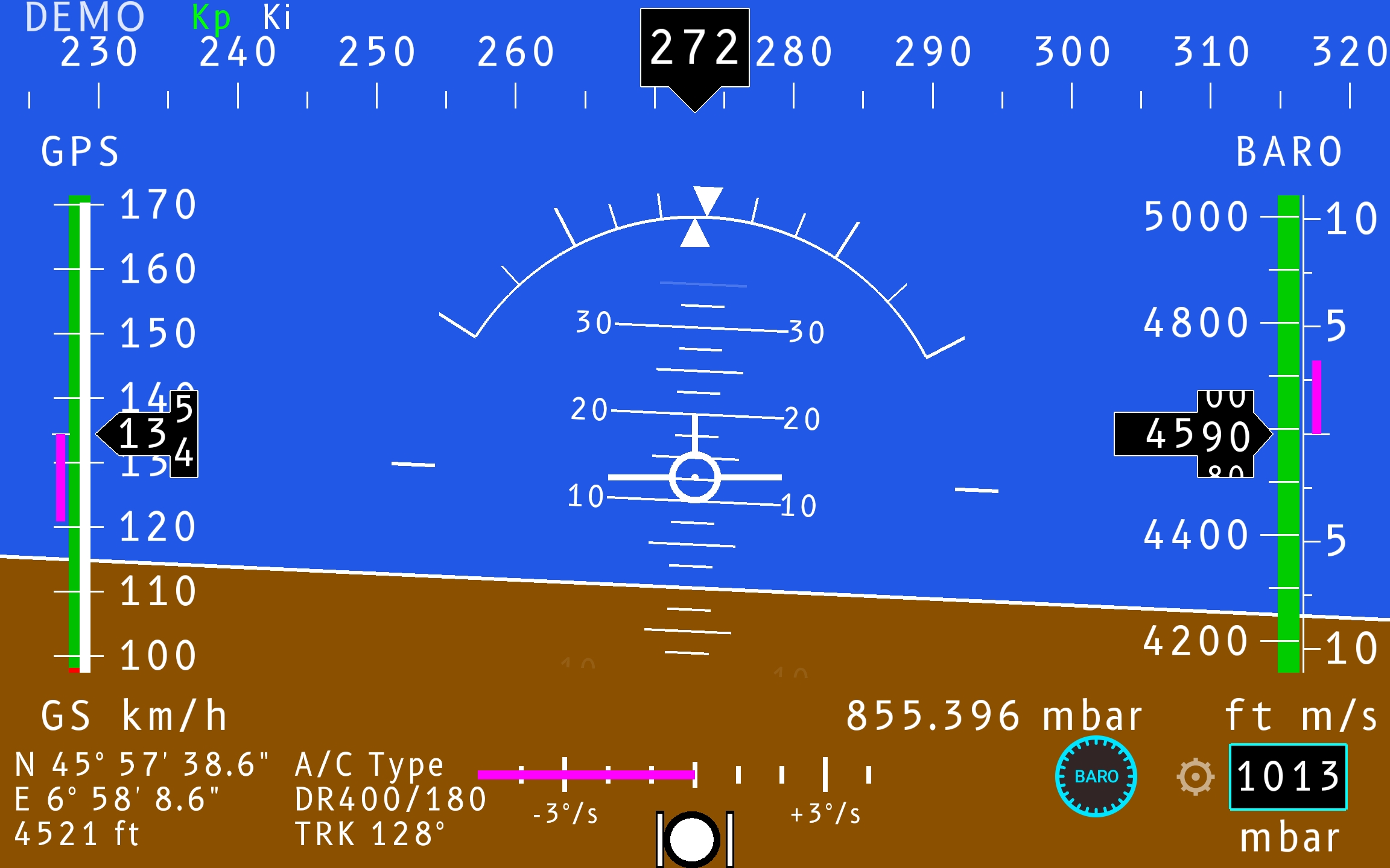
A Primary Flight System consolidates the essential instruments of a light aircraft into one picture. The artificial horizon splits the screen — sky above, ground below; speed runs down the left, altitude down the right, heading across the top, supplementary data along the bottom.
 1
2
3
4
5
6
7
8
9
10
11
13
12
14
15
1
2
3
4
5
6
7
8
9
10
11
13
12
14
15
| Top strip | heading & compass tape |
|---|---|
| Center | artificial horizon, pitch ladder, bank, aircraft symbol |
| Left tape | ground speed (GPS) & 6 s trend (km/h, kt or mph) |
| Right tape | altitude (ft or m), vertical speed (m/s or fpm) |
| Bottom-left | position, GPS altitude, A/C type & V-speeds, ground track |
| Bottom-center | turn & slip, rate-of-turn scale |
| Bottom-right | altimeter setting (mbar or inHg), unit labels, configurable aux field |
The artificial horizon shows pitch and bank relative to the earth's horizon. The blue/brown boundary is the horizon line; a fixed aircraft symbol in the centre is the reference for reading both.
Pitch ladder
Horizontal bars at 10°, 20°, 30° above and below the horizon.
Bank scale
Arc with ticks at 10°, 20°, 30°, 45° and 60°; the pointer shows current bank.
Speed — left
Altitude & vertical speed — right
Heading
The compass tape runs across the top; heading is read under the central pointer, in 10° steps. It is fused from the Inertial Measurement Unit (IMU) magnetometer and shown as magnetic heading (°M) by default, or true heading (°T) with the local declination applied — selectable in Settings.
Turn & slip
The rate-of-turn scale is marked −3°/s and +3°/s with a magenta bar; the ball below is the slip/skid indicator — centred means coordinated flight.
| Latitude & longitude | from GPS fix |
|---|---|
| GPS altitude | ft or m (independent of baro) |
| A/C type | e.g. DR400/180 |
| Ground track (TRK) | °, true over the ground |
| Auxiliary zone | QNH & static pressure (mbar or inHg) |
Selectable windows
Bottom fields can show battery voltage, local time and more — chosen in Settings.
GPS vs baro altitude
GPS altitude is shown alongside barometric altitude as an independent cross-check.
Demo mode
A "DEMO" tag marks synthetic data; the Kp/Ki status flags show live correction activity — and turn red as an alarm when corrections stay blind too long.