Work in progress This site is under construction — content, figures and specifications are provisional.
2 — Features

Six instruments,
four estimators.

Every element is drawn in OpenGL ES 3 from a single per-frame state snapshot — a crisp, low-latency display that stays readable in direct sunlight.
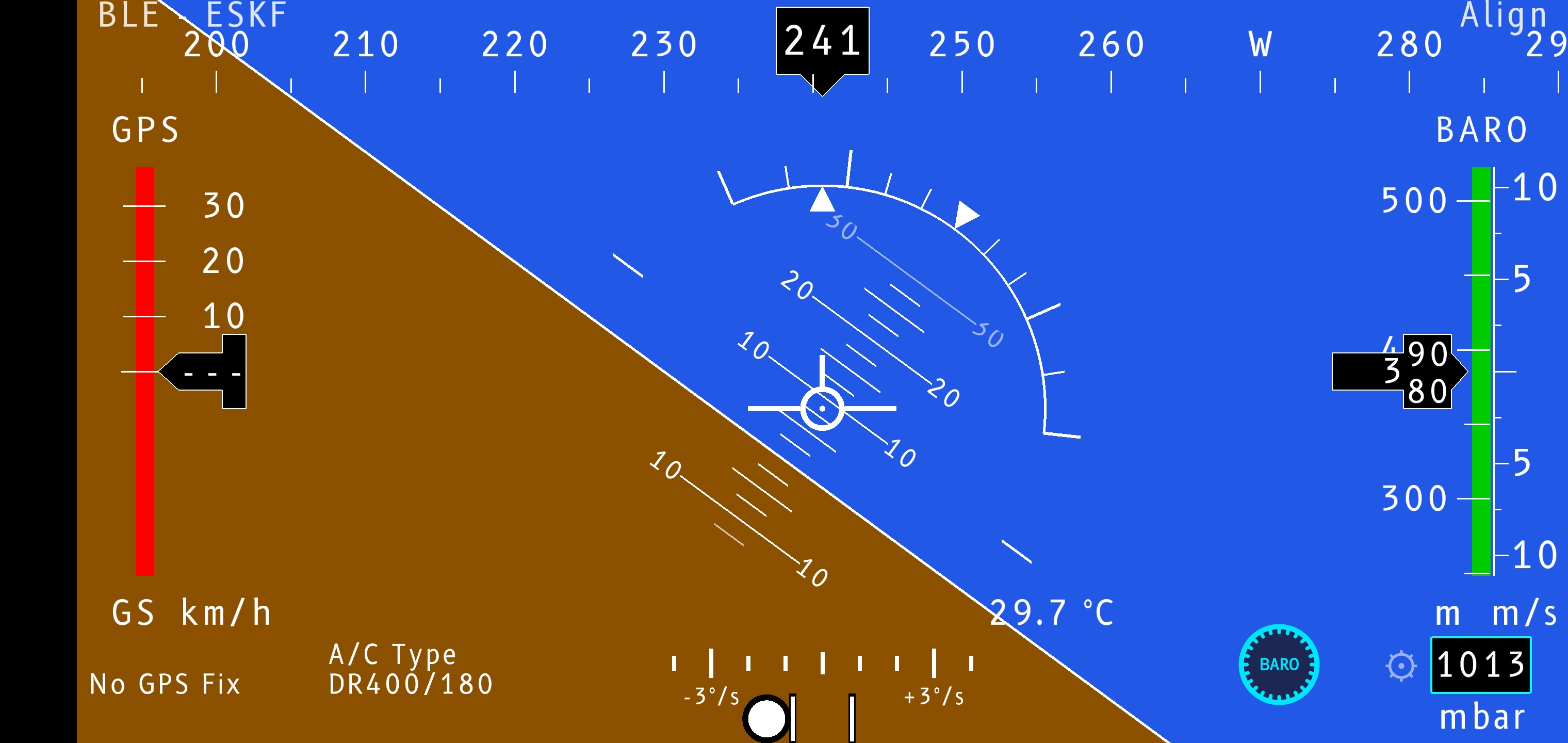
InstrumentsAttitude first.
Fig.01 — The displaylive, ESKF
FlySys PFS showing attitude, tapes and heading band
Artificial horizon
bank & pitch, pitch ladder
Ground-speed tape
GPS (km/h, kt or mph)
Altitude tape
barometric (ft or m)
Vertical speed
dedicated Vertical Speed Indicator (VSI), m/s or fpm (feet per minute)
Heading band
Inertial Measurement Unit (IMU)-fused, magnetic (°M) or true (°T)
Slip & turn
coordinate the turn
RenderingOpenGL ES — optimised.

The display is drawn in OpenGL ES 3 from a single per-frame state snapshot. The pipeline is built for a steady, low-power, allocation-free frame — so the picture stays smooth and the battery lasts.

Fig.05 — Render pipelinerender-on-dirty
DISPLAY STATE per-frame state SUB-RENDERERS horizon, ladder, roll, tapes, vertical speed, heading, slip BATCHED GEOMETRY zero per-frame alloc few draw calls GPU redraw only on change, up to 60 Hz (vsync-bound)
One state snapshot fans out to focused sub-renderers, batched into few allocation-free draw calls sent to the GPU (Graphics Processing Unit). Frames are issued only when the state changes.
01

Render-on-dirty

A frame is drawn only when the state actually changes — selectable 30 Hz battery-saver, or uncapped 60 Hz bounded by vsync. The IMU streams up to 250 Hz (configurable, or synced to the display rate); the filters run at whatever the stream delivers.

02

Zero per-frame allocation

No objects are allocated while drawing, so there are no garbage-collection stalls — motion stays smooth.

03

Batched triangles

Geometry is accumulated and submitted in a few large draw calls instead of many small ones.

04

Cached geometry

Shapes whose parameters haven't changed reuse their cached vertices instead of rebuilding.

05

Shared GL resources

One shader program and a shared text atlas serve every instrument — minimal state changes.

06

Pre-allocated matrices

Attitude matrices live for the lifetime of the renderer, reused every frame.

PrinciplesHow the attitude is computed.

No single sensor gives a trustworthy attitude. The gyroscope is fast but drifts; the accelerometer and magnetometer are stable on average but noisy and disturbed by manoeuvre. Every estimator below resolves the same conflict — trust the gyro over short intervals, correct it toward gravity and magnetic north over long ones — and they differ only in how they strike that balance. Each is presented in its own section below, in the order they appear in Settings.

Error-state Kalman§1 — ESKF, default.
Fig.02 — Error-state Kalman filterESKF (default)
GYRO ω, TEMP T z: accel, mag, GPS, baro 1 — PREDICT propagate state x propagate covariance P 2 — UPDATE Kalman gain K δx from innovation 3 — INJECT & RESET apply error δx reset δx ATTITUDE q, bias, k_T(T)
The gyro propagates a nominal state openly; the Kalman filter tracks only the small error it accumulates, then injects the correction and resets — keeping the error small is what keeps the linearisation valid.

The gyro propagates attitude fast; every other sensor only ever applies a small correction. The accelerometer anchors pitch and roll from gravity — but it is gated off the instant a sustained turn or linear acceleration makes "down" untrustworthy. What keeps the bank true under load is a set of independent EKF (Extended Kalman Filter) measurement updates, each watching a different quantity and weighted by its own confidence. Its state carries not only the quaternion and gyro bias but a per-device temperature coefficient — the IMU's temperature is logged and fed in, so the bias it removes tracks the sensor as it warms. This is the default estimator.

Fig.02b — Measurement updatesmulti-aided
ACCEL — gravity direction anchors pitch & roll, gated in turns MAG — heading tilt-compensated, pure yaw, no tilt leak GPS TURN — bank bank = atan(V·ω / g), coordinated turn LOAD FACTOR — bank bank = acos(1 / N), from g-load, no GPS BARO & GPS-ALT — pitch pitch = asin(VSI / V) + AoA GPS TRACK — yaw heading fallback when no magnetometer EKF UPDATE innovation z − h(x) K weighted by σ δx = K · innovation ATTITUDE q, bias, k_T
Six independent sources, each weighted by its own σ. The two bank updates — GPS coordinated-turn and load factor (acos 1/N) — are what hold a true bank through a turn, where the accelerometer alone can't.
Predict — gyro, with a temperature-tracked bias
b_{\text{eff}}(T) = b_g + k_T\,(T - T_{\text{ref}}) \qquad P \leftarrow F\,P\,F^{\mathsf{T}} + Q
Update — every source forms an innovation, weighted by its own σ
K = P\,H^{\mathsf{T}}\bigl(H P H^{\mathsf{T}} + R\bigr)^{-1} \qquad \delta x = K\,\bigl(z - h(\hat{x})\bigr)
Bank — two independent measurements that survive a turn
\phi = \arctan\!\frac{V\,\omega}{g}\ \ (\text{GPS turn}) \qquad \phi = \arccos\frac{1}{N},\ \ N=\frac{a_z}{g}\ \ (\text{load factor})
Pitch — from the flight-path angle; α₀ is the angle of attack (AoA)
\theta = \arcsin\!\frac{\mathrm{VSI}}{V} + \alpha_0
Inject & reset
x \leftarrow \hat{x} \oplus \delta x \qquad \delta x \leftarrow 0
Complementary§2 — CF, Mahony-MARG.
Fig.03 — Complementary, Mahony-MARGCF
GYRO ω fast, drifts INTEGRATE gyro propagation ACCEL+MAG gravity & north ERROR e measured vs estimated CORRECTION P & I feedback ATTITUDE roll, pitch, yaw

A Mahony-MARG filter (Magnetic, Angular-rate, Gravity) splits the signal by frequency: the gyro supplies the fast motion, accel and mag the slow reference. The correction is the rotation error between measured and estimated gravity/north, fed back through a proportional and an integral gain — and the integral term also learns and cancels gyro bias. Cheap, robust and predictable — the simple, dependable fallback.

Rotation error, then corrected propagation
e \;=\; \hat{v}_g \times v_g \;+\; \hat{v}_m \times v_m
\dot{q} \;=\; \tfrac{1}{2}\, q \otimes \Bigl(\omega + K_p\, e + K_i \!\!\int e\, dt \Bigr)
Madgwick§3 — MG, gradient descent.
Fig.04 — MadgwickMG (gradient)
GYRO ω orientation rate FUSE gyro & gradient ACCEL+MAG gravity & north OBJECTIVE f alignment error GRADIENT STEP descent rate β ATTITUDE roll, pitch, yaw

Frames orientation as an optimisation: the gyro gives the rate, while a single gradient-descent step nudges the estimate toward the orientation that best matches measured gravity and north — at one tunable rate, β. Smooth and responsive for very little compute.

Objective, gradient, and the fused rate
f(q) \;=\; R(q)^{\mathsf{T}}\, \hat{g} \;-\; a \qquad \nabla f = J^{\mathsf{T}} f
\dot{q} \;=\; \tfrac{1}{2}\, q \otimes \omega \;-\; \beta\, \frac{\nabla f}{\lVert \nabla f \rVert}
Firmware quaternion§4 — FW, pass-through.
Fig.05 — Internal, firmware quaternionFW (pass-through)
IMU SENSOR on-board fusion QUATERNION q already fused PASS-THROUGH no phone filter ATTITUDE

When the IMU already publishes its own fused quaternion, this mode passes it straight to the display — a useful reference, and the right choice when you trust the sensor's on-board fusion over the phone's.

Pass-through — no phone-side estimation
q \;=\; q_{\text{IMU}}
Data sourcesFly, sim, or replay.
BLE Waveshare 10-DOFexternal IMU (primary)
Internal sensorsphone accel, gyro, mag, baro
X-Plane UDPsimulator feed
FlySys TCPTCP gateway
Replayrecorded CSV from Documents/PFS/
Demosynthetic motion (no hardware)
CalibrationThree sensors.
01

Magnetometer

Hard- and soft-iron fit so heading stays honest near metal and avionics.

02

Accelerometer

A guided 6-face procedure recovers per-axis offset and scale, applied before the filters.

03

Gyro offset

A short static "Align" window zeroes gyro bias the moment you power up on the ground.